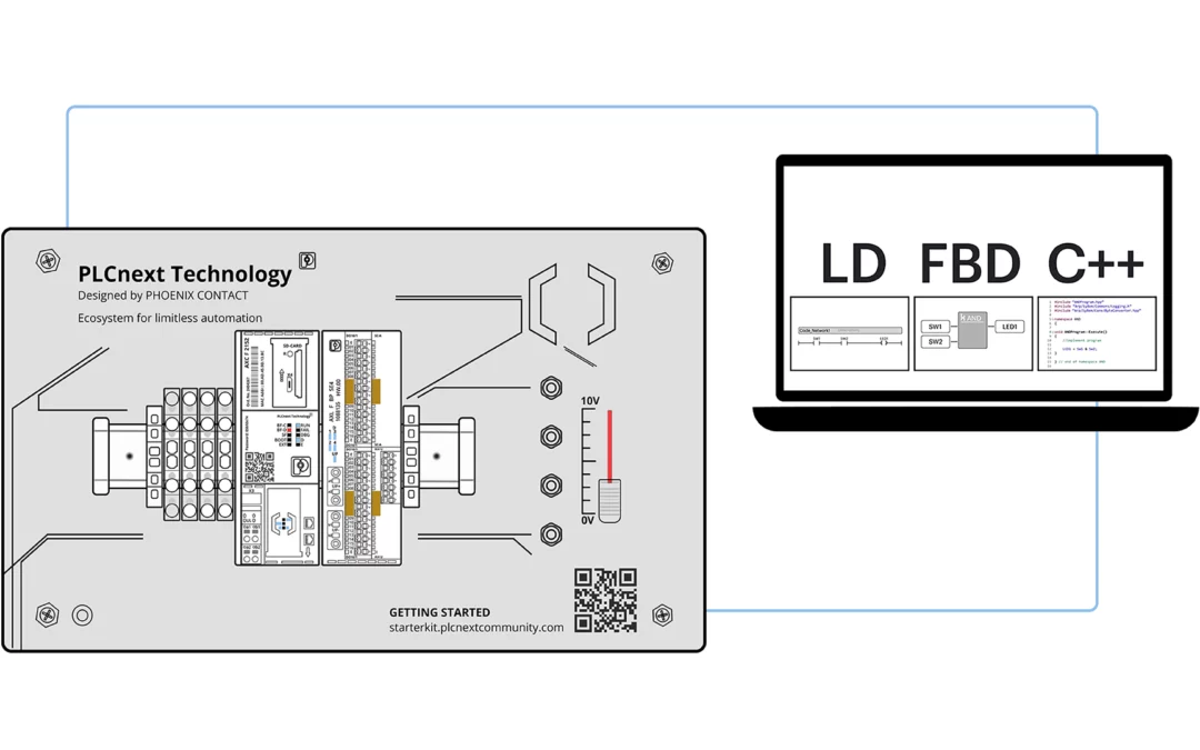
we're going to use 3 different PLC programming languages to solve one problem. We’re going to use 2 IEC 61131-3 languages and a higher-level language called C++.
The IEC 61131's five programming languages specified in the IEC 61131-3 Standard are Ladder Diagram, Instruction List, Function Block Diagram, Structured Text, and Sequential Function Chart. We are going to use Ladder Diagram and Function block in our exercise.
Ladder Diagram was the first language developed for PLC programming. The simple explanation for why Ladder Diagram programming became so popular was that it closely resembled traditional “Relay Logic Diagrams”.
Electricians and Engineers alike were familiar and comfortable with Relay Logic Diagrams and easily adapted to Ladder Diagrams.
Early Ladder Diagram programming involved entering typical relay-type symbols onto a rung via hand-held programming devices connected to a PLC. It wasn’t long before computers and Graphical User Interfaces made this process much easier.
This was all well and fine until more complex PLC hardware and I/O were developed and programming languages needed to advance thus spawning Function Block and other languages.
More complex functions are not easily accomplished with traditional IEC 61131-3 languages and require higher-level languages such as C++ which is a familiar language in the world of IT programmers.
For example, C++ programs can be easily created to produce “logged data” to assist with “Predictive Maintenance” (PdM). A program of that complexity cannot be easily created using Ladder Diagram.
We want an LED to turn on when two normally-open pushbutton switches are operated.
- The ladder diagram has 2 open contacts operated by SW1 and SW2 on the Starterkit. Operating the “coil” output will turn on LED1 on the digital output module. Operating SW1 and SW2 switches will close normally open contacts, energize the coil and cause LED1 to turn on.
- Basic blocks of FBD are based on “Logic Operators” such as AND, OR, and NOT. The FBD to solve our problem is built around an AND Function Block.
- Eclipse IDE can be used as C++ Editor. Because C++ is not an IEC 61131-3 language, it is not a programming choice available in PLCnext Engineer. With a few simple tools, a C++ project created in Eclipse can be imported into a PLCnext Engineer project.
Physically there's no difference in operation between any of the 3 programs we used to solve our problem.
What programming language should you use?
There’s really no single correct answer as there isn’t one best PLC programming language.
It’s apparent that we wouldn’t use C++ to solve the simple problem presented in this exercise as Ladder Diagram or Function Block are easier and more appropriate.
Each language has its strengths and weaknesses and degrees of suitability for specific applications and of course, the challenge is to choose the correct one.
Ut wisi enim ad minim veniam, quis nostrud exerci tation ullamcorper suscipit lobortis nisl ut aliquip ex ea commodo consequat. Duis autem vel eum iriure dolor in hendrerit in vulputate velit esse molestie consequat.
A special and comprehensive blog in the field offers all the news in the world of technology and Android applications and programs, as well as all those related to Acton, which help you in your study and your work and solve all the problems related to electronic technology. So don't hesitate to leave us everything you want to know in the comments or contact us.


No comments:
Post a Comment