How to reduce 12v voltage to 5v with resistor || simple voltage regulator
In this, you can convert 12v to 9v converter for making projects of 9v Rechargeable batteries and so on.
Components Required:
7809 Voltage Regulator - 1 pcs
2 pin PCB Connector - 2 pcs
Steps to Connect:
Connect 12v +ve voltage to 7809 Vin pin and -ve to 7809 GND pin.
You will get the output of 9v at Vout pin.
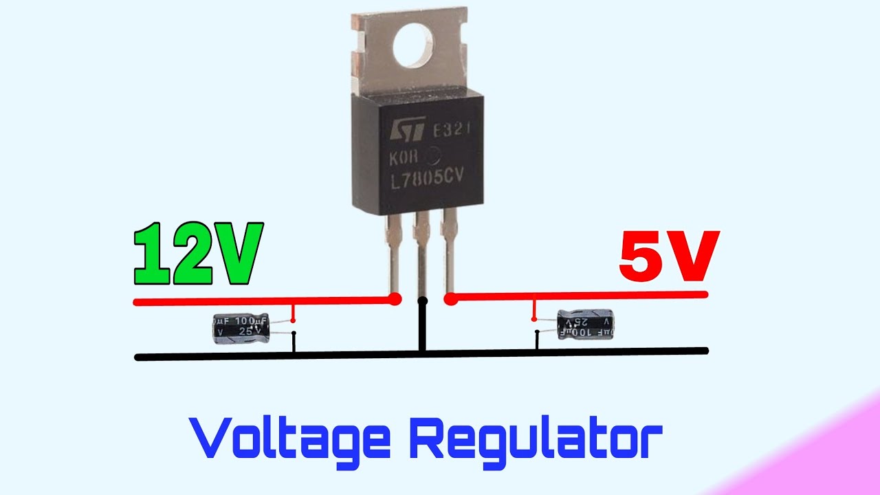
For Arduino and other Microcontrollers, we have to give an input voltage of 5v. If your battery or power supply gives an output of 12v , we should convert 12v to 5v for Arduino, Raspberrypi etc.
Components Required:
7805 Voltage Regulator - 1 pcs
2 pin PCB Connector - 2 pcs
Steps to Connect:
Connect 12v +ve voltage to 7805 input pin and -ve to 7805 GND pin.
You will get the output of 5v at output pin.
You can also give 12v or 9v as input voltage.
In NodeMCU WiFi microcontroller, we have to give an input voltage of 3.3v. You can down the voltage from 12v to 5v using 7805 IC. If you want to convert the 5v to 3.3v, this tutorial will surely help you to convert 5v to 3.3v.
Components Required:
7805 Voltage Regulator - 1 pcs
1k Resistor - 1 pcs
2.2k Resistor - 1 pcs
Steps to Connect:
1. Connect 5v input to 1k Resistor
2. Connect 1k Resistor another end to 2.2k Resistor.
3. 1k Resistor another end and 2.2k another end are connected to Multimeter and test the result.
In most devices, particularly NodeMCU WiFi microcontroller gives the output voltage of 3.3v. The 3.3v output sometimes can't trigger the heavy elements like Motor or the output connects with several triggering elements. In order to avoid this, we need to convert 3.3v to 5v.
Components Required:
1 K ohm Resistor - 1 pcs
2N3904 Transistor - 1 pc
5v Power Supply
Steps to Connect:
1. Connect 3.3v GPIO pin to 1k Resistor
2. Other end of 1k Resistor connect to 2N3904 Transistor(Base)
3. 2N3904 Transistor (Emitter) is connected to Ground
4. 2N3904 Transistor (Collector) connect to one end of Multimeter.
5. 5v +ve supply connect to other end of Multimeter.
6. 5v -ve supply connect to ground.
Both the circuit diagrams are the same. Don't confuse.
Conclusion
Finally we designed the circuit and make sure that your circuit should be tested in Breadboard after that you can go for the Soldering in PCB or Dot Board. It is tested and verified the results. See you next time to my Next Project. If you have any queries kindly ask in the comments, we will clarify you at any time.
How to reduce 12v voltage to 5v with resistor || simple voltage regulator
In this, you can convert 12v to 9v converter for making projects of 9v Rechargeable batteries and so on.
Components Required:
7809 Voltage Regulator - 1 pcs
2 pin PCB Connector - 2 pcs
Steps to Connect:
Connect 12v +ve voltage to 7809 Vin pin and -ve to 7809 GND pin.
You will get the output of 9v at Vout pin.
For Arduino and other Microcontrollers, we have to give an input voltage of 5v. If your battery or power supply gives an output of 12v , we should convert 12v to 5v for Arduino, Raspberrypi etc.
Components Required:
7805 Voltage Regulator - 1 pcs
2 pin PCB Connector - 2 pcs
Steps to Connect:
Connect 12v +ve voltage to 7805 input pin and -ve to 7805 GND pin.
You will get the output of 5v at output pin.
You can also give 12v or 9v as input voltage.
In NodeMCU WiFi microcontroller, we have to give an input voltage of 3.3v. You can down the voltage from 12v to 5v using 7805 IC. If you want to convert the 5v to 3.3v, this tutorial will surely help you to convert 5v to 3.3v.
Components Required:
7805 Voltage Regulator - 1 pcs
1k Resistor - 1 pcs
2.2k Resistor - 1 pcs
Steps to Connect:
1. Connect 5v input to 1k Resistor
2. Connect 1k Resistor another end to 2.2k Resistor.
3. 1k Resistor another end and 2.2k another end are connected to Multimeter and test the result.
In most devices, particularly NodeMCU WiFi microcontroller gives the output voltage of 3.3v. The 3.3v output sometimes can't trigger the heavy elements like Motor or the output connects with several triggering elements. In order to avoid this, we need to convert 3.3v to 5v.
Components Required:
1 K ohm Resistor - 1 pcs
2N3904 Transistor - 1 pc
5v Power Supply
Steps to Connect:
1. Connect 3.3v GPIO pin to 1k Resistor
2. Other end of 1k Resistor connect to 2N3904 Transistor(Base)
3. 2N3904 Transistor (Emitter) is connected to Ground
4. 2N3904 Transistor (Collector) connect to one end of Multimeter.
5. 5v +ve supply connect to other end of Multimeter.
6. 5v -ve supply connect to ground.
Both the circuit diagrams are the same. Don't confuse.
Conclusion
Finally we designed the circuit and make sure that your circuit should be tested in Breadboard after that you can go for the Soldering in PCB or Dot Board. It is tested and verified the results. See you next time to my Next Project. If you have any queries kindly ask in the comments, we will clarify you at any time.


No comments:
Post a Comment