To be honest, transmission and distribution networks are full of problems. But that’s nothing new, and you already knew that. This technical article will shed some light on solving some pretty severe problems in transmission and distribution networks by using reactive power (VAr) compensators.
The voltage drop in an AC electric power supply system, caused by problem loads which are large compared with the short circuit level of the system, is mainly due to reactive component of the load flowing through the system reactance.
The variations in loads can cause voltage fluctuations and consequent objectionable or irritating light flicker. These troublesome loads sometimes produce , which are large enough to cause distortion problems to other consumers whose electricity supply is provided from the same busbar (the point of common coupling).
To provide in order to support the power supply system voltage and to filter the harmonic currents in accordance with Electricity Authority recommendations, which prescribe the permissible voltage fluctuations and harmonic distortions, reactive power (VAr) compensators are required.
The speed of response of the synchronous compensator is low and the cost is high when compared with the static VAr compensators and hence the latter are the preferred solution.
Static var compensator (SVC) is a shunt connected static var generator or absorber whose output is adjusted to exchange capacitive or inductive current to maintain or control specific parameters of the electrical power system (typically bus voltage).
Static var compensator system provides dynamic reactive power and is directly connected to the bus of an electric appliance. Maximum SVC’s reactive power is generated by capacitors of harmonic filters and is equal to maximum reactive power of the appliance.
Response time of the SVC control system to changes of controlled parameters is 5 ms for EAF and 25-100 ms for general industrial applications and transformer substations.
SVC control and protection system allows unmanned operation of the equipment. Rated power and combination SVC device components are defined for particular projects depending on parameters of the power supply system as well as type and power of compensated load.
The Power Transmission Division of GEC, Stafford, was the pioneer of saturated reactor type compensator. The saturated reactor type compensators were first developed in the 1960’s by AREVA (then GEC) under the guidance of Dr. E. Friedlander. These are transformer type devices, which were built in the factory of AREVA (then GEC) Transformers Limited in Stafford.
It does so by the nature of the saturation feature of the of its core iron as it operates normally in saturated flux region. The saturated reactor is inherent in its response and the speed of response is fast. The reactive power required for compensation is generated by parallel connected shunt capacitance (often in the form of tuned or damped harmonic filters).
The order of harmonic filters depends primarily on the harmonic (number) currents generated by the troublesome loads.
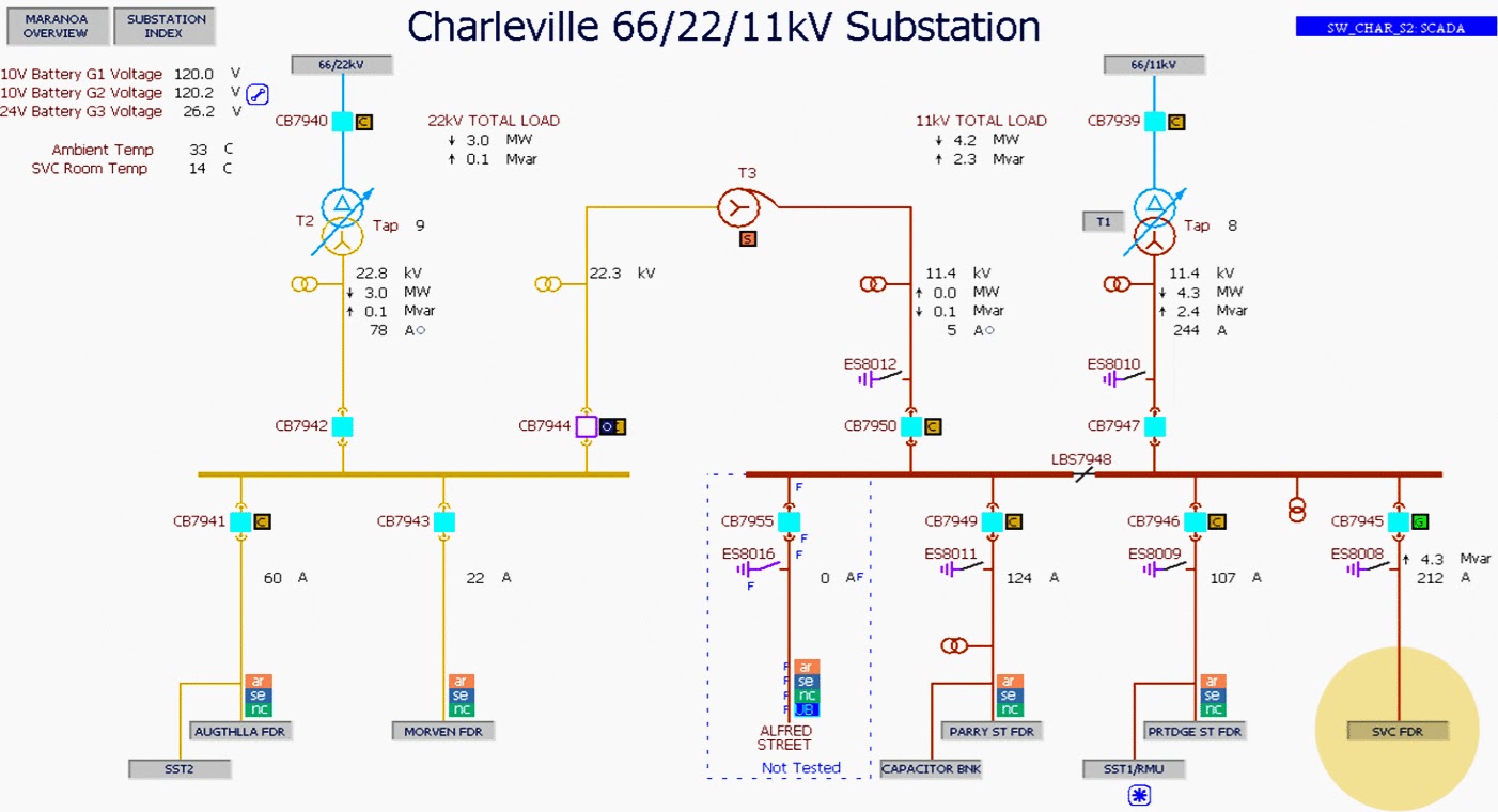
The SVC installed in Substation ‘‘ performs the function of maintaining stable voltages at both high and low load times. At low load times, without the SVC in service, significant voltage rise would occur on the Charleville area network.
Similarly, without the SVC’s capacitive support, voltage would become low during high load periods.
At peak load times, without the SVC in service, some loads may also need to be shed in order to maintain a suitable voltage.
Figure 3 above provides an overview of Charleville substation basic configuration.
Thyristor controlled reactor (TCR) is a whose effective reactance is varied in a continuous manner by partial conduction of the thyristor valve. The thyristor controlled reactor comprises a linear reactor, connected in series with a ‘thyristor valve’ made up of inverse-parallel (back-to-back) connected pairs of high power, high voltage thyristors.
In saturated reactor . In a TCR the current is switched by thyristors. As in the case of a saturated reactor compensator, the reactor power required by the loads is generated by parallel connected shunt capacitance (as mentioned above, often in the form of harmonic filters).
During system light load conditions, the excess reactive power from this shunt capacitance is absorbed by thyristor controlled reactor. The design of the depends on the harmonic generated by both the thyristor compensator and the problem loads.
The major harmonic frequencies which the TCR produces in the AC supply depend on the , (e.g. p = 6) in accordance with the formula where stands for the harmonic number and is a positive integer.
To be honest, transmission and distribution networks are full of problems. But that’s nothing new, and you already knew that. This technical article will shed some light on solving some pretty severe problems in transmission and distribution networks by using reactive power (VAr) compensators.
The voltage drop in an AC electric power supply system, caused by problem loads which are large compared with the short circuit level of the system, is mainly due to reactive component of the load flowing through the system reactance.
The variations in loads can cause voltage fluctuations and consequent objectionable or irritating light flicker. These troublesome loads sometimes produce , which are large enough to cause distortion problems to other consumers whose electricity supply is provided from the same busbar (the point of common coupling).
To provide in order to support the power supply system voltage and to filter the harmonic currents in accordance with Electricity Authority recommendations, which prescribe the permissible voltage fluctuations and harmonic distortions, reactive power (VAr) compensators are required.
The speed of response of the synchronous compensator is low and the cost is high when compared with the static VAr compensators and hence the latter are the preferred solution.
Static var compensator (SVC) is a shunt connected static var generator or absorber whose output is adjusted to exchange capacitive or inductive current to maintain or control specific parameters of the electrical power system (typically bus voltage).
Static var compensator system provides dynamic reactive power and is directly connected to the bus of an electric appliance. Maximum SVC’s reactive power is generated by capacitors of harmonic filters and is equal to maximum reactive power of the appliance.
Response time of the SVC control system to changes of controlled parameters is 5 ms for EAF and 25-100 ms for general industrial applications and transformer substations.
SVC control and protection system allows unmanned operation of the equipment. Rated power and combination SVC device components are defined for particular projects depending on parameters of the power supply system as well as type and power of compensated load.
The Power Transmission Division of GEC, Stafford, was the pioneer of saturated reactor type compensator. The saturated reactor type compensators were first developed in the 1960’s by AREVA (then GEC) under the guidance of Dr. E. Friedlander. These are transformer type devices, which were built in the factory of AREVA (then GEC) Transformers Limited in Stafford.
It does so by the nature of the saturation feature of the of its core iron as it operates normally in saturated flux region. The saturated reactor is inherent in its response and the speed of response is fast. The reactive power required for compensation is generated by parallel connected shunt capacitance (often in the form of tuned or damped harmonic filters).
The order of harmonic filters depends primarily on the harmonic (number) currents generated by the troublesome loads.
The SVC installed in Substation ‘‘ performs the function of maintaining stable voltages at both high and low load times. At low load times, without the SVC in service, significant voltage rise would occur on the Charleville area network.
Similarly, without the SVC’s capacitive support, voltage would become low during high load periods.
At peak load times, without the SVC in service, some loads may also need to be shed in order to maintain a suitable voltage.
Figure 3 above provides an overview of Charleville substation basic configuration.
Thyristor controlled reactor (TCR) is a whose effective reactance is varied in a continuous manner by partial conduction of the thyristor valve. The thyristor controlled reactor comprises a linear reactor, connected in series with a ‘thyristor valve’ made up of inverse-parallel (back-to-back) connected pairs of high power, high voltage thyristors.
In saturated reactor . In a TCR the current is switched by thyristors. As in the case of a saturated reactor compensator, the reactor power required by the loads is generated by parallel connected shunt capacitance (as mentioned above, often in the form of harmonic filters).
During system light load conditions, the excess reactive power from this shunt capacitance is absorbed by thyristor controlled reactor. The design of the depends on the harmonic generated by both the thyristor compensator and the problem loads.
The major harmonic frequencies which the TCR produces in the AC supply depend on the , (e.g. p = 6) in accordance with the formula where stands for the harmonic number and is a positive integer.


No comments:
Post a Comment