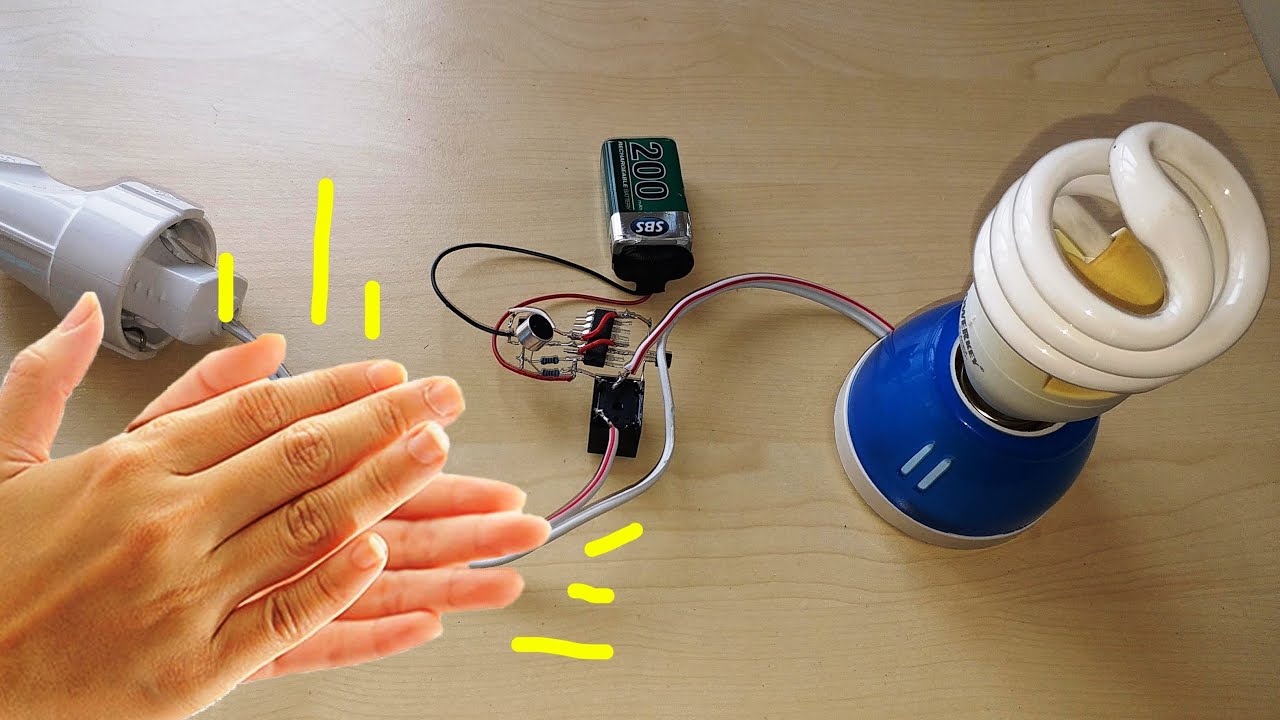
What is a Clap Switch Circuit?
A clap switch is a simple electronic circuit project that allows the user to gain dynamic control of AC/DC appliances. It receives sound signals as an input and converts them into an electrical signal, which can then be used to control devices such as lighting fixtures, relays, small appliances, etc. So in today's tutorial, we are going to go over a step by step process on how to design a Clap Switch Circuit Project Using LM358 Op-Amp And CD4017 counter IC.
LM358 IC
An LM358 is a simple operational amplifier that is integrated with two amplifiers that are powered by using a single power supply. The IC offers an outstanding value for cost-sensitive applications, with features including low offset (300 µV, typical), common-mode input range to ground, and high differential input voltage capability. They are commonly used in applications such as integrators, differentiators, summer adders, voltage followers, and oscilloscopes, etc.
CD4017 IC
The heart of this Clap Switch Circuit is a CD4017 IC. A CD4017 IC is a 16 pin CMOS decade counter/Divider IC with 10 outputs. It is also known as the 'Johnson 10 stage decade counter'. It has 10 decoded outputs that give output signals one by one in sequence when a clock signal from the clock input is given. Its input includes a CLOCK, a RESET, and a CLOCK INHIBIT signal. Schmitt trigger action in the CLOCK input circuit provides pulse shaping that allows unlimited clock input pulse rise and fall times.


No comments:
Post a Comment