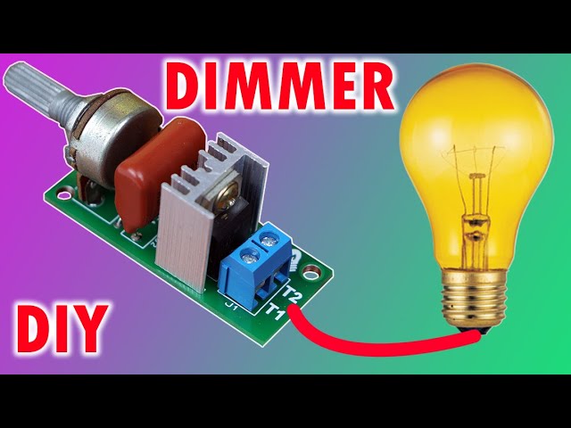
light dimmer
A Dimmer, regulator or light attenuator, is used to regulate the energy in one or several light bulbs, in order to vary the intensity of the light they emit, when the properties of the lamp make it possible.
Currently, the most widely used circuits include the voltage “crossing zero” ignition function. The reduction of the effective value in the bulb is achieved by cutting the signal at the moment of rise at the point that is chosen (if we cut the signal when the wave reaches 60 V p.e. it will turn on very little, while if we cut it when it reaches 120V will turn on near full).
1-Arduino nano
1-MOC3021 Optocoupler
1- Triac 10 amps at 800 volts – QL8010L5
1-220 ohm resistor
3-pin 2-pin connectors
1-5k potentiometer with knob
1-button normally open for embedding
1-9 volt voltage source to power the Arduino uno
cables, heatsink for the triac, power cables to connect to the alternating current line.
EXPLANATION OF THE PROJECT
This project Dimmer power light controller with Arduino, consists of controlling your light through the RV1 potentiometer, this potentiometer is in charge of sending a current level to pin A0 of the Arduino, so that the program interprets the increase or decrease of voltage
taken by pin A0 and converts it into a signal that will decrease or increase, offering it by output pin 9.
This pin number 9 is the one that gives the saturation signal for pin number 2 of the optocoupler up to this point we already know
What does the potentiometer and the optocoupler do? Now, if we look at the program, this will be the order that will take the reading and issue it through output pin 9 as shown below.
The potentiometer, as seen in the figures, has 3 pins, where pin 1 at the end is connected to GND, pin 2 in the center goes to pin A0 of the Arduino and pin 3 at the other end is connected to the 5 volt vcc. .
This circuit is responsible for turning the light bulb on or off, it only has 2 pins, which pin 1 is connected to GND (negative) and pin 2 is connected to pin number 6 of the Arduino uno. This circuit takes a logic Zero and sends it to pin 6 of the Arduino and the program determines when a pulse is generated, to emit through the output pin number 13 of the Arduino and this is the one who saturates the led diode of the optocoupler and will be the one who generates a logic 1 to turn the bulb on or a logic 0 to turn it off. In the program the structure would be the following:
Let's start, by parts, from the MOC3021 optocoupler.
It is an emission and reception device that works as a switch activated by the light emitted by an LED diode that saturates
an optoelectronic component, usually in the form of a phototransistor or phototriac. In this way they are combined in a single device
semiconductor, a photoemitter and a photoreceptor whose connection between them is optical. These items are in a
Encapsulation that is generally of the DIP type. They are often used to electrically isolate very sensitive devices.
The MOC3021-M consists of a gallium arsenide infrared emitting diode optically coupled to a silicon bilateral switch. This device is designed for use in applications that require isolated TRIAC tripping.
Being so; pin 1 is the one that receives the logical state of turning off and on from pin number 13 of the Arduino.
Pin number 2 of the optocoupler is the one that receives the signal that comes from the RV1 potentiometer that comes out of pin number 9 of the Arduino and is the one that will increase or decrease the light intensity in the bulb.


No comments:
Post a Comment