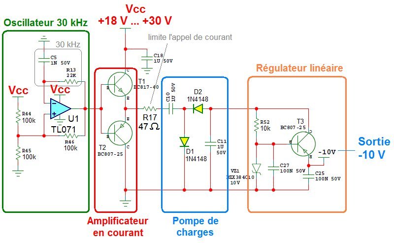
How to make a simple current amplifier circuit
multitude of devices: loudspeaker, electric motor, antenna, instrument, display,
other electronic circuits. ´
In the concept of amplification, the amplifier should reproduce the input signal
in all its variations, with greater voltage and current and with fidelity (without ´
distortion). Ex: the term Hi-Fi (or High Fidelity) designates systems with outputs that
look like inputs (for audio systems). `
Most electrical signals requiring amplification are in the form of
plex and have different frequency components. Example: the signal representing
speech or music, obtained at the output of a microphone, has the frequency range ´
from 20Hz to 20kHz. Such a signal can be treated as the sum of a large number of
sinusoids. Each sinusoid has its own frequency, amplitude and phase. ´
Theoretically, one can reconstruct any form of signal by summing ´
an appropriate number of sinusoidal signals (Fourier series). ´
In the study of amplifiers, it is often considered that the signals are simple
(1 frequency, sine wave) and not complex shaped signals. Most often used
linear amplifiers, which makes it possible to exploit the principle of superposition: the ´
output of an amplifier is the sum of the outputs obtained by amplifying each
separate components forming the input.
Figure 1.2 – Example of decomposition and amplification ´
With the decomposition, it is possible to predict the behavior of the amplifier
frequency at a time. We can therefore decompose the signal and analyze each component of ´
individual way to get the complete output signal
1.2 Polarization
For transistor-based amplifiers, the power supply often has a single
polarity. On the other hand, the input and output voltage must often be positive or negative. ´
To accommodate this particularity, the AC signal should be superimposed on a signal
CC. This is the goal of polarization:
v(t) = vdc + Vp sin(ωt) (1.1)
Figure 1.3 shows an example of DC voltage added to a signal to obtain a
output which is only positive.
1.3 DC/AC Equivalent Circuits ´
When analyzing an amplifier having a signal composed of a CC part and a ´
AC signal, the equivalent circuit may be different depending on the analysis. There will be a circuit
DC equivalent and an AC equivalent circuit, which are not necessarily the same. We
uses the principle of superposition to do the analysis:
– If we consider the DC signal, the AC source is shorted. ´
– If we consider the AC signal, the DC source is short-circuited. ´
The analysis is therefore done in two parts: a DC analysis, and an AC analysis.


No comments:
Post a Comment