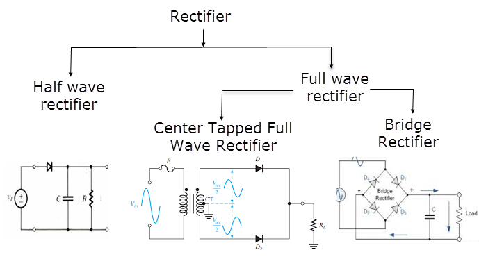
One of the most popular applications of the diode is rectification. The rectifier is a device that converts an alternating current (AC) to pulsating direct current (DC). This pulsating DC has some ripples in it that can remove by using a smoothing capacitor. Different types of rectifiers given below: This article discusses “Why full wave rectifier is better than a full wave center tap rectifier”. In full wave bridge rectifier, the whole input waveform is utilized when compared to half wave rectifier. Whereas in half wave rectifiers only half wave is utilized. The full wave rectifier can be constructed in two ways. One is center tapped full wave rectifier consisting of two diodes and one center tapped secondary winding transformer and the second is a Bridge Rectifier consisting of four diodes namely D1, D2, D3, D4 connected.
Types of Rectifiers
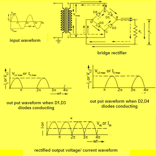
Working of Full Wave Bridge Rectifier
The bridge rectifier is constructed by using 4 diodes in the form of a Wheatstone bridge which is fed by a step-down transformer. When a step downed AC supply fed through the bridge, it is seen that during the positive half cycle of secondary supply the diodes D1 and D3 (Shown in below figure) are in forward biased. And the diodes D2 & D4 will not conduct. So the current will pass through the diode D1, load (R), and diode D3. And vice versa during the negative half cycle of secondary input. Generally, an AC input is in the form of the sinusoidal waveform (sin(wt)). The output waveform and circuit diagram is shown below.
Working of a Bridge Rectifier
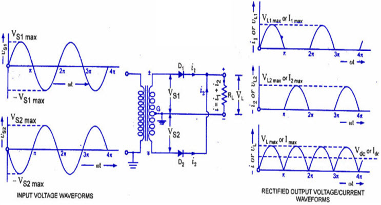
Working of Center Tapped Full Wave Rectifier
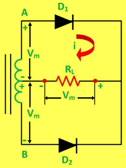
The center tapped full wave rectifier is build with a center tapped transformer and two diodes D1 and D2, are connected as shown in below figure. When the AC power supply switched ON, the voltage appearing across the terminals AB of transformer secondary terminal side. During the positive half cycle, the diode D1 is in forward bias and the diode D2 is in reverse bias, it won’t conduct. So the current will pass through the diode D1 and Load (R). During the negative cycle of the secondary cycle, only the diode D2 will conduct and current will pass through the diode D2 and the Load (R).
Working of Center Tapped Full Wave Rectifier
Why is a Full Wave Bridge Rectifier better than a Full Wave Center Tapped Rectifier?
A bridge rectifier does not require a bulky center tapped transformer, nowadays the center tapped transformers are costlier than diodes and a step-down transformer hence reduced size and cost.
The PIV (peak inverse voltage) ratings of the diodes in bridge rectifier is half than that of needed in a center tapped full wave rectifiers. The diode used in bridge rectifier has capable of bearing high peak inverse voltage. Whereas in center tapped rectifiers, the peak inverse voltage coming across each diode is double the maximum voltage across the half of the secondary winding.
The transformer utilization factor (TUF) also more in bridge rectifier as compared to the center tapped full wave rectifier, Which makes it more advantageous.
PIV (peak inverse voltage) of Bridge Rectifier
PIV: For rectifiers, Peak inverse voltage(PIV) or peak reverse voltage(PRV) can be defined as the maximum value of the reverse voltage of a diode, which occurs at the peak of the input cycle when the diode is in reverse bias.
PIV of Bridge Rectifier
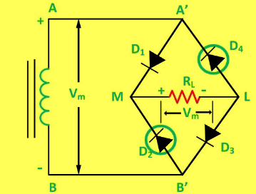
When the secondary voltage gets its peak positive value and the terminal A is positive, and B is negative as shown in above. So at this instant, the diode D1 and D3 are forward biased and D2 and D4 are in reverse bias they won’t conduct, but only the diodes D1 &D3 will conduct current through them. Therefore, in between the terminal M-L or A’-B’ gets the same voltage as that the terminals A-B.
Therefore the PIV of bridge rectifiers is
PIV of diode D1 and D3 = Vm
Similarly PIV of diode D2 and D4 = Vm
PIV (peak inverse voltage) of Center Tapped Full Wave Transformer
During the first half cycle of the AC power supply, i.e. when the top of the transformer secondary winding is positive, the diode D1 conducts and offers almost zero resistance. So the whole the voltage Vm max of the upper half winding is developed across the load (RL). Now the voltage across the non-conducting diode D2 is the sum of the voltage across the lower half of the transformer secondary and the voltage across the load (RL).
PIV of Center Tapped
Thus, PIV of diode, D2 = Vm + Vm
PIV of diode, D2 = 2 Vm
Similarly, PIV of diode D1 = 2 Vm
Transformer utilization Factor (TUF)
TUF is defined as the ratio of DC power delivered to the load and the input AC rating of the transformer secondary.
TUF= Poutput.dc/Pinput.ac
Transformer Utilization Factor (TUF) of the Center Tapped Full-wave Rectifier
Pdc = VL(dc)*IL(dc) => VLM/π *VLM/RL
=> VLM2 /πRL
=> Vsm2 /πRL (if drop over R0 is neglected)
Now, the rated voltage of the transformer secondary is given by Vsm/√2 but the actual current flowing through the secondary is IL = ILM/2 (not ILM /√2) since it is a Half-Wave rectifier current.
Pac.rated => Vsm/√2 *ILM/2
=> Vsm/√2* VLM/2RL
=> Vsm/2√2RL
Its value is found by considering the primary and secondary winding of the transformer separately. Its value is 0.693.
Transformer Utilization Factor of Bridge Rectifier
Pdc => VL(dc).IL(dc)
=> VLM/π * VLM/RL => VLM2 /πRL
=> Vsm2 /πRL (if drop over R0 is neglected)
Now, the rated voltage of the transformer secondary is Vsm/√2 but the actual current flowing through the secondary is IL = ILM/2 (not ILM /√2) since it is a Half-Wave rectifier current.
Pac = Vsm/√2 *ILM/2
=> Vsm/√2 *VLM/2RL
=> Vsm/2√2RL
Its value is found by considering the primary and secondary winding of the transformer separately. Its value is 0.812
The differences between center tapped full wave rectifier and bridge rectifier
Parameters
Center tapped full wave rectifier
Bridge rectifier
Number of diodes
2
4
Maximum efficiency
81.2%
81.2%
Peak inverse voltage
2Vm
Vm
Vdc(no load)
2Vm/π
2Vm/π
Transformer utilization factor
0.693
0.812
Ripple factor
0.48
0.48
Form factor
1.11
1.11
Peak factor
√2
√2
Average current
Idc/2
Idc/2
Output frequency
2f
2f
Thus, this is all about the differences between full wave bridge rectifier and center tapped full wave rectifier. We hope that you have got a better understanding of this concept. Furthermore, any queries regarding this concept or to know more about thyristor or SCR. Please give your feedback by commenting in the comment section below. Here is a question for you, What is the function of a bridge rectifier?
One of the most popular applications of the diode is rectification. The rectifier is a device that converts an alternating current (AC) to pulsating direct current (DC). This pulsating DC has some ripples in it that can remove by using a smoothing capacitor. Different types of rectifiers given below: This article discusses “Why full wave rectifier is better than a full wave center tap rectifier”. In full wave bridge rectifier, the whole input waveform is utilized when compared to half wave rectifier. Whereas in half wave rectifiers only half wave is utilized. The full wave rectifier can be constructed in two ways. One is center tapped full wave rectifier consisting of two diodes and one center tapped secondary winding transformer and the second is a Bridge Rectifier consisting of four diodes namely D1, D2, D3, D4 connected.
Types of Rectifiers
Working of Full Wave Bridge Rectifier
The bridge rectifier is constructed by using 4 diodes in the form of a Wheatstone bridge which is fed by a step-down transformer. When a step downed AC supply fed through the bridge, it is seen that during the positive half cycle of secondary supply the diodes D1 and D3 (Shown in below figure) are in forward biased. And the diodes D2 & D4 will not conduct. So the current will pass through the diode D1, load (R), and diode D3. And vice versa during the negative half cycle of secondary input. Generally, an AC input is in the form of the sinusoidal waveform (sin(wt)). The output waveform and circuit diagram is shown below.
Working of a Bridge Rectifier
Working of Center Tapped Full Wave Rectifier
The center tapped full wave rectifier is build with a center tapped transformer and two diodes D1 and D2, are connected as shown in below figure. When the AC power supply switched ON, the voltage appearing across the terminals AB of transformer secondary terminal side. During the positive half cycle, the diode D1 is in forward bias and the diode D2 is in reverse bias, it won’t conduct. So the current will pass through the diode D1 and Load (R). During the negative cycle of the secondary cycle, only the diode D2 will conduct and current will pass through the diode D2 and the Load (R).
Working of Center Tapped Full Wave Rectifier
Why is a Full Wave Bridge Rectifier better than a Full Wave Center Tapped Rectifier?
A bridge rectifier does not require a bulky center tapped transformer, nowadays the center tapped transformers are costlier than diodes and a step-down transformer hence reduced size and cost.
The PIV (peak inverse voltage) ratings of the diodes in bridge rectifier is half than that of needed in a center tapped full wave rectifiers. The diode used in bridge rectifier has capable of bearing high peak inverse voltage. Whereas in center tapped rectifiers, the peak inverse voltage coming across each diode is double the maximum voltage across the half of the secondary winding.
The transformer utilization factor (TUF) also more in bridge rectifier as compared to the center tapped full wave rectifier, Which makes it more advantageous.
PIV (peak inverse voltage) of Bridge Rectifier
PIV: For rectifiers, Peak inverse voltage(PIV) or peak reverse voltage(PRV) can be defined as the maximum value of the reverse voltage of a diode, which occurs at the peak of the input cycle when the diode is in reverse bias.
PIV of Bridge Rectifier
When the secondary voltage gets its peak positive value and the terminal A is positive, and B is negative as shown in above. So at this instant, the diode D1 and D3 are forward biased and D2 and D4 are in reverse bias they won’t conduct, but only the diodes D1 &D3 will conduct current through them. Therefore, in between the terminal M-L or A’-B’ gets the same voltage as that the terminals A-B.
Therefore the PIV of bridge rectifiers is
PIV of diode D1 and D3 = Vm
Similarly PIV of diode D2 and D4 = Vm
PIV (peak inverse voltage) of Center Tapped Full Wave Transformer
During the first half cycle of the AC power supply, i.e. when the top of the transformer secondary winding is positive, the diode D1 conducts and offers almost zero resistance. So the whole the voltage Vm max of the upper half winding is developed across the load (RL). Now the voltage across the non-conducting diode D2 is the sum of the voltage across the lower half of the transformer secondary and the voltage across the load (RL).
PIV of Center Tapped
Thus, PIV of diode, D2 = Vm + Vm
PIV of diode, D2 = 2 Vm
Similarly, PIV of diode D1 = 2 Vm
Transformer utilization Factor (TUF)
TUF is defined as the ratio of DC power delivered to the load and the input AC rating of the transformer secondary.
TUF= Poutput.dc/Pinput.ac
Transformer Utilization Factor (TUF) of the Center Tapped Full-wave Rectifier
Pdc = VL(dc)*IL(dc) => VLM/π *VLM/RL
=> VLM2 /πRL
=> Vsm2 /πRL (if drop over R0 is neglected)
Now, the rated voltage of the transformer secondary is given by Vsm/√2 but the actual current flowing through the secondary is IL = ILM/2 (not ILM /√2) since it is a Half-Wave rectifier current.
Pac.rated => Vsm/√2 *ILM/2
=> Vsm/√2* VLM/2RL
=> Vsm/2√2RL
Its value is found by considering the primary and secondary winding of the transformer separately. Its value is 0.693.
Transformer Utilization Factor of Bridge Rectifier
Pdc => VL(dc).IL(dc)
=> VLM/π * VLM/RL => VLM2 /πRL
=> Vsm2 /πRL (if drop over R0 is neglected)
Now, the rated voltage of the transformer secondary is Vsm/√2 but the actual current flowing through the secondary is IL = ILM/2 (not ILM /√2) since it is a Half-Wave rectifier current.
Pac = Vsm/√2 *ILM/2
=> Vsm/√2 *VLM/2RL
=> Vsm/2√2RL
Its value is found by considering the primary and secondary winding of the transformer separately. Its value is 0.812
The differences between center tapped full wave rectifier and bridge rectifier
Parameters
Center tapped full wave rectifier
Bridge rectifier
Number of diodes
2
4
Maximum efficiency
81.2%
81.2%
Peak inverse voltage
2Vm
Vm
Vdc(no load)
2Vm/π
2Vm/π
Transformer utilization factor
0.693
0.812
Ripple factor
0.48
0.48
Form factor
1.11
1.11
Peak factor
√2
√2
Average current
Idc/2
Idc/2
Output frequency
2f
2f
Thus, this is all about the differences between full wave bridge rectifier and center tapped full wave rectifier. We hope that you have got a better understanding of this concept. Furthermore, any queries regarding this concept or to know more about thyristor or SCR. Please give your feedback by commenting in the comment section below. Here is a question for you, What is the function of a bridge rectifier?
Software tester We always follow the latest trends in IT world and update our syllabus based on that information. Our students graduate with the knowledge of the latest technology that is used in Software Development and QA.
Ut wisi enim ad minim veniam, quis nostrud exerci tation ullamcorper suscipit lobortis nisl ut aliquip ex ea commodo consequat. Duis autem vel eum iriure dolor in hendrerit in vulputate velit esse molestie consequat.
A special and comprehensive blog in the field offers all the news in the world of technology and Android applications and programs, as well as all those related to Acton, which help you in your study and your work and solve all the problems related to electronic technology. So don't hesitate to leave us everything you want to know in the comments or contact us.


thanks
ReplyDeleteSoftware tester We always follow the latest trends in IT world and update our syllabus based on that information. Our students graduate with the knowledge of the latest technology that is used in Software Development and QA.
ReplyDelete