
The RLC Series Circuit is defined as when a pure resistance of R ohms, a pure inductance of L Henry and a pure capacitance of C farads are connected together in series combination with each other. As all the three elements are connected in series so, the current flowing in each element of the circuit will be same as the total current I flowing in the circuit.
L
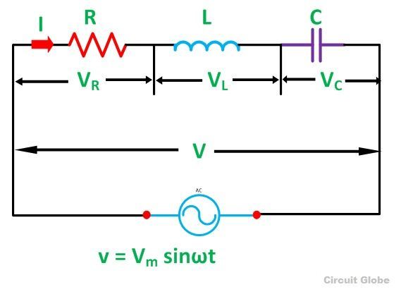
The RLC Circuit is shown below
In the RLC Series Circuit
XL = 2πfL and XC = 1/2πfC
When the AC voltage is applied through the RLC Series Circuit the resulting current I flows through the circuit, and thus the voltage across each element will be
- VR = IR that is the voltage across the resistance R and is in phase with the current I.
- VL = IXL that is the voltage across the inductance L and it leads the current I by an angle of 90 degrees.
- VC = IXC that is the voltage across the capacitor C and it lags the current I by an angle of 90 degrees.
Phasor Diagram of RLC Series Circuit
The phasor diagram of the RLC Series Circuit when the circuit is acting as an inductive circuit that means (VL>VC) is shown below and if (VL< VC) the circuit will behave as a capacitive circuit.
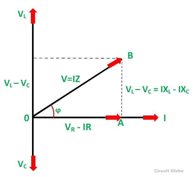
Steps to draw the Phasor Diagram of the RLC Series Circuit
- Take current I as the reference as shown in the figure above
- The voltage across the inductor L that is VL is drawn leads the current I by a 90-degree angle.
- The voltage across the capacitor c that is Vc is drawn lagging the current I by a 90 degree angle because in capacitive load the current leads the voltage by an angle of 90 degrees.
- The two vector VL and VC are opposite to each other.
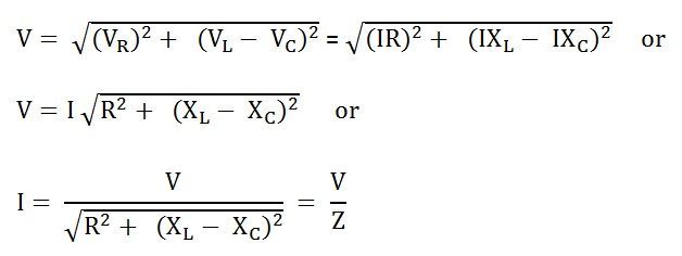
Where,

It is the total opposition offered to the flow of current by an RLC Circuit and is known as Impedance of the circuit.
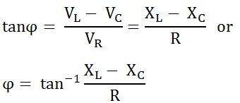
Phase Angle
Phase Angle
Power in RLC Series Circuit
The product of voltage and current is defined as power.
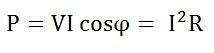

Where cosϕ is the power factor of the circuit and is expressed as

The three cases of RLC Series Circuit
- When XL > XC, the phase angle ϕ is positive. The circuit behaves as a RL series circuit in which the current lags behind the applied voltage and the power factor is lagging.
- When XL < XC, the phase angle ϕ is negative, and the circuit acts as a series RC circuit in which the current leads the voltage by 90 degrees.
- When XL = XC, the phase angle ϕ is zero, as a result, the circuit behaves like a purely resistive circuit. In this type of circuit, the current and voltage are in phase with each other. The value of power factor is unity.
Impedance Triangle of RLC Series Circuit
When the quantities of the phasor diagram are divided by the common factor I then the right angle triangle is obtained known as impedance triangle. The impedance triangle of the RL series circuit, when (XL > XC) is shown below
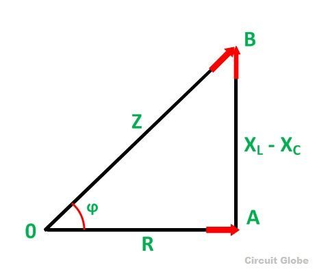
If the inductive reactance is greater than the capacitive reactance than the circuit reactance is inductive giving a lagging phase angle.
Impedance triangle is shown below when the circuit acts as a RC series circuit (XL< XC)
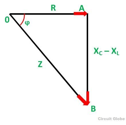
When the capacitive reactance is greater than the inductive reactance the overall circuit reactance acts as a capacitive and the phase angle will be leading.
The RLC Series Circuit is defined as when a pure resistance of R ohms, a pure inductance of L Henry and a pure capacitance of C farads are connected together in series combination with each other. As all the three elements are connected in series so, the current flowing in each element of the circuit will be same as the total current I flowing in the circuit.
L
The RLC Circuit is shown below
In the RLC Series Circuit
XL = 2πfL and XC = 1/2πfC
When the AC voltage is applied through the RLC Series Circuit the resulting current I flows through the circuit, and thus the voltage across each element will be
- VR = IR that is the voltage across the resistance R and is in phase with the current I.
- VL = IXL that is the voltage across the inductance L and it leads the current I by an angle of 90 degrees.
- VC = IXC that is the voltage across the capacitor C and it lags the current I by an angle of 90 degrees.
Phasor Diagram of RLC Series Circuit
The phasor diagram of the RLC Series Circuit when the circuit is acting as an inductive circuit that means (VL>VC) is shown below and if (VL< VC) the circuit will behave as a capacitive circuit.
Steps to draw the Phasor Diagram of the RLC Series Circuit
- Take current I as the reference as shown in the figure above
- The voltage across the inductor L that is VL is drawn leads the current I by a 90-degree angle.
- The voltage across the capacitor c that is Vc is drawn lagging the current I by a 90 degree angle because in capacitive load the current leads the voltage by an angle of 90 degrees.
- The two vector VL and VC are opposite to each other.
Where,
It is the total opposition offered to the flow of current by an RLC Circuit and is known as Impedance of the circuit.
Phase Angle
Phase Angle
Power in RLC Series Circuit
The product of voltage and current is defined as power.
Where cosϕ is the power factor of the circuit and is expressed as
The three cases of RLC Series Circuit
- When XL > XC, the phase angle ϕ is positive. The circuit behaves as a RL series circuit in which the current lags behind the applied voltage and the power factor is lagging.
- When XL < XC, the phase angle ϕ is negative, and the circuit acts as a series RC circuit in which the current leads the voltage by 90 degrees.
- When XL = XC, the phase angle ϕ is zero, as a result, the circuit behaves like a purely resistive circuit. In this type of circuit, the current and voltage are in phase with each other. The value of power factor is unity.
Impedance Triangle of RLC Series Circuit
When the quantities of the phasor diagram are divided by the common factor I then the right angle triangle is obtained known as impedance triangle. The impedance triangle of the RL series circuit, when (XL > XC) is shown below
If the inductive reactance is greater than the capacitive reactance than the circuit reactance is inductive giving a lagging phase angle.
Impedance triangle is shown below when the circuit acts as a RC series circuit (XL< XC)
When the capacitive reactance is greater than the inductive reactance the overall circuit reactance acts as a capacitive and the phase angle will be leading.


Thanks more
ReplyDelete